


Improving energy efficiency is becoming increasingly important to today’s industrial companies. The benefits are reduced operational costs (leading to increased profitability) and reduced impact on the environment. The International Standards Organization recognizes the importance of energy management in the ISO-50001 Standard for Energy Management Systems. Increasingly, companies are making a commitment to energy efficiency by staffing energy management, or sustainability positions often at a senior board level. Proactive businesses have found that reviewing energy use in each link of the supply chain can deliver significant benefits.
This blog will focus on the impact of mechanical seals and their support systems on energy usage in the Pulp and Paper making process, it should be note that the topic discussed is also relevant in other industries.
The Impact of Mechanical Seals
Mechanical seals consume energy. They are components which prevent fluid leakage from the shaft region of process pumps and other rotating equipment. The vast majority of mechanical seals are deployed in process pumps at refineries, petrochemical plants, pulp and paper plants and a host of other industries. With the exception of gas-injecting seals (available on very few pumping services), mechanical seals often are set-up with a clean flush liquid in the seal cavity to provide lubrication, prevent overheating and maximize reliability. This flush liquid is provided from a separate source and the way that this flush is configured can influence the amount of fluid used, the amount of energy consumed and also affect equipment reliability.
The objective of a periodic audit is to identify and quantify the monetary value associated with upgrading your seals and sealing support systems. An effective audit will also consider equipment reliability and project energy savings. The audit details energy improvement opportunities associated with alternative flush liquid piping plans. In the pulp and paper industry seal water piping plans deserve special attention, and in particularly focus on the cost of reheating and/or evaporation of seal water, where seal water is injected into the process stream. The cost to reheat and further evaporate this injected seal water can be eliminated simply by using the right flush plan and the technology exists to eliminate injected seal water.
Mechanical Seal Support Systems
The selection of the seal support system configuration (often termed ‘Piping plan’) is made in isolation. Plant maintenance reliability personnel select plans to prolong the life and reliability of the equipment. Operational stakeholders, responsible for energy consumption, have limited visibility of how a seal piping plan impacts energy usage and energy efficiency. To understand this impact it is useful to perform a seal energy audit.
Seal Energy Audit
A seal energy audit requires inspection of each piece of equipment, recording seal arrangement, support system configuration, process data and seal system parameters (e.g. water flow, temperature etc). Having collated the existing plant data and performing heat flow calculations it is then possible to calculate the amount of energy impact of each and every mechanical seal on the plant. High energy usage can be easily identified and reviewed to see if a more efficient configuration is appropriate. Table 1 below illustrates a typical summary from an audit report that identifies potential opportunities, the investment required to upgrade and the potential returns.
| Scope of Savings Priorities | Energy Cost Savings | Estimated Upgrade Investment | Return On Investment Summary |
|---|---|---|---|
| Priority 1: Chemical Recovery Boiler Evaporators. Check Water Injection points on pumps tied to 6 Effect Evaporators. Scope of savings – 100 GPM injection elimination on 130°F temperature using $4.00 / 1,000 lbs of steam and 85% Evaporator Efficiencies saves 50,000 MMBTU’s | $250K to $360K | $150k | < 5 Months to < 7 Months Evaporator Limited Mills improve throughput |
| Priority 2: Condensate Recovery Pumps Inspection of Separation Pumps operating with continuous leakage. Scope of savings – 10,000 lbs/hour loss on 8000 operating hours with average boiler efficiency of 80% and makeup water of 55°F | Water Sewage and Chemicals: $34K Annual Fuel Savings: $88K Total: $122K | $50,000 | < 5 Months |
| Priority 3: Reheat Applications including Pulp Mill and Kamyr Continuous Digesters, requiring continuous high pressure seal water injection ranked by differential temperature and GPM injection rates | 8 GPM typical for excess Injection $20K Reheat | Variable | Typically < 9 Months |
Table 1: Typical Format of recommendations delivered in a typical Seal Energy Survey
Example: Evaluating Seal Support System Configurations
The focus of this article is where the opportunity for significant energy savings and reliability improvements can be accurately identified. In the pulp and paper industry one such area is where a plan 32 configuration is used (Fig 1).
A Plan 32 configuration involves injecting a clean or cool liquid from an external source directly into the seal chamber. Plan 32 can be used with mechanical packing and single mechanical seals.
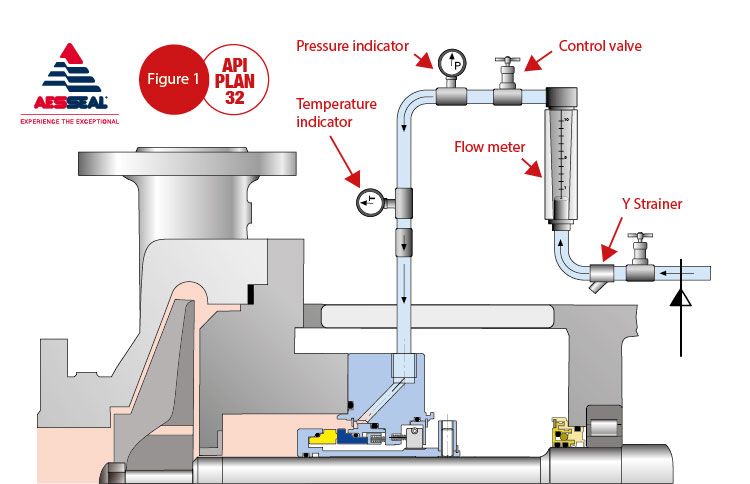
From an energy point of view, this configuration is costly to operate.
As the Figure 1 illustrates, a control valve and flow meter control the volume of water injected. Often it is found that these controls are removed because of clogging due to particulates and turbidity in the seal water. Typical flows can be seen in table 2 below.
| Plan 32 Pipe Size Schedule 40 | GPM Low Pressure | GPM (20-100psi) | GPM High Pressure |
|---|---|---|---|
| 1/2" ID | 7 | 14 | 21 |
| 3/4" ID | 11 | 23 | 36 |
| 1" ID | 16 | 37 | 58 |
Table 2 Flow Estimates (Reference: http://www.slideshare.net/raju175/water-flow-pipe-sizes )
Quantifying the losses
Quantifying energy losses is part of getting the whole picture, and the starting point is to record temperatures. Reading and graphically representing these temperatures is made easy with thermography. The temperature scale shows the difference between the process temperature and the injected seal water.
If the process contains water and the final product is paper or concentrated liquor to fuel a recovery boiler, the water must ultimately be removed. And regardless of how the water is squeezed out or evaporated, energy will be consumed. In this example of the pulp and paper pump application, seal water is injected at 80°F (Fig. 2).
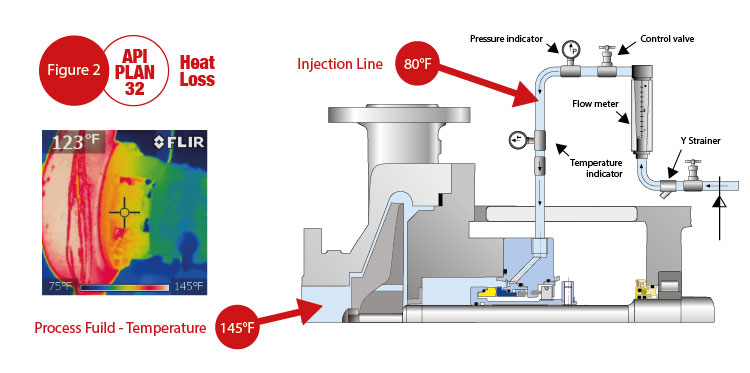
A thermal imaging camera is targeted at the seal chamber; it records a temperature of 123°F. This temperature is less than the process temperature; and the reduction is caused by the 80°F water being injected through the support system as illustrated in the graphic. This seal water must be reheated to 145° F, meaning extra energy is required to stabilize the process temperature.
The energy cost is the frictional energy consumed by the seal or packing, plus the pump heat soak, and the energy consumed in additional downstream processes to remove flush-to-process dilution and/or restore process temperature. Note that for the actual example cited here the calculation predicted energy losses of 38.145 kW due to heat soak. According to FSA/ESA (Fluid Sealing Association / European Sealing Association) Life-Cycle Cost Estimator/Version 4.1 and using the built-in program defaults, this equates to an energy cost of $ 33,293/year per application.
It is important to have a full perspective on the energy impact of friction; the direct power consumption is $130 for a single mechanical seal and $1,298 for mechanical packing. This compares to the heat soak of $33,293; in other words the heat soak factor is 256 times greater than the direct power cost of a single seal.
Reliability considerations, however, also involve knowing the quality of the seal water system to ensure that it is appropriate.
Reducing flush water injection
In principle flow control could be used to reduce the amount of water injected, however, merely reducing the rate of flush water injection tends to compromise seal life. In addition operator vigilance must be heightened to more closely control (and verify) that reduced water injection rates does not cause seal failures. Demands for increased operator vigilance and/or narrowing the allowable pump seal environment range will increase the risk of incurring equipment downtime and process outages.
The FSA comments (as published in Pumps & Systems Magazine, October 2007) on API Plan 32 flush arrangements and reminds users that the flush fluid must be compatible with the liquid or slurry being pumped. The flush fluid will enter the process and will, in most instances, have to be removed so as to restore process fluid integrity. Actual costs go beyond initial purchase cost or even the costs associated with reclaiming separated diluents. For these reasons, Plan 32 is very rarely recommended today.
The potential savings achieved by reducing the flush flow rate from 8GPM to 1GPM for an application at 150°F, and steam costs of $5.00/1000 lbs of steam will reduce the energy cost from $62,905 to $7,862 / year. While this is a significant saving, the cost is still almost $8K per year, and the operator must ensure that the water is of suitable quality in order to ensure equipment reliability.
Typical seal water standards are:
- No Impurities, such as clay, smaller than 10 micrometers
- No particles larger than 50 micrometers
- No more than 10 milligrams of silicate content per liter
- No more than 30 milligrams of organic impurities per liter
- No more than 1 milligram of iron per liter
- The total water hardness should be lower than 10 degrees dH (medium hardness)
However the situation can be improved significantly by upgrading mechanical packing or the single seal to a dual seal along with a seal support system in a modified Plan 53A configuration (Figure 3). This configuration will reduce water usage to zero in normal operation.
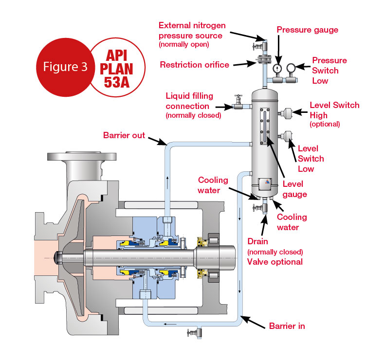
Plan 53
Plan 53 is a pressurized barrier fluid circulation system for a dual seal configuration. It is used to control the fluid film formation between the inner seal faces in order to extend seal life. Plan 53 operates with a “barrier” fluid at a pressure higher than the seal chamber. This means the barrier fluid is the fluid film at the inner seal face set.
Self-contained water management systems.
Today’s advanced self-contained water management systems are superior to other approaches from a life-cycle cost point-of-view. These systems are both cost-effective and environmentally friendly. Most important, they represent best practice technology in every sense of the word.
A Water Management System effectively combines two piping configurations: (Plan 53-A and Plan 54). These advanced combined-plan systems maintain a fluid film over the seal faces (improving seal reliability) while consuming virtually no water in normal operation. The systems may cost more to install than simple flush configurations, because they eliminate process cooling and dilution, they reduce energy usage. The resultant savings are many times more than the initial cost of the system.
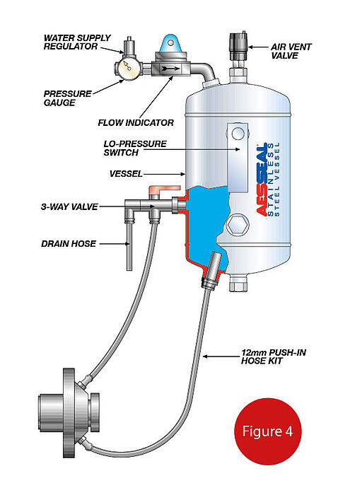
In a water management system (figure 4) the tank is mounted above the seal application. System pressure is controlled by a regulator on the top of the tank and feed water is connected directly to the tank from a water header or water main. If there is a loss of barrier fluid, the water source connection automatically recharges the system. A flow indicator on top of the tank verifies that water is not entering into the heated process. Water quality is controlled by using an in-line filter prior to the regulator. The filter can be replaced on-line. Replacement is infrequent because the filter does not see continuous flow of water, which makes it possible to improve filtration from 50-microns down to an optimal 1-micron.
The Water Management System removes the requirement to have the operator manually check and fill the tank because it is self-filling. Continuous pressurization of the barrier fluid ensures the fluid film is always a clean and cool liquid giving optimal seal life.
Summary
Significant energy saving (and subsequent cost savings) can be readily evaluated in many applications through the use of a mechanical seal energy audit. The results of the audit can identify the low hanging opportunities, that with minimal investment can deliver significant reductions in energy usage and improve seal (and consequently pump) reliability. Developments in mechanical seal support systems have delivered simple solutions that are proven to deliver. For more information on seal energy audits, watch our short demonstration video.